Multi-Contact MA265 Benutzerhandbuch
Seite 6
Advanced Contact Technology
Advanced Contact Technology
10 / 16 www.multi-contact.com
www.multi-contact.com
11 / 16
15
16
17
N
18
Montage der Paneldose auf das PV-Modul
Mounting the junction box on the PV module
(ill. 15)
Nach dem Anlöten des Flachbandleiters die Paneldosen-
aufnahme nach vorne schwenken, bis der vorgespannte
Arretierbolzen in einer seitlichen Bohrung der Paneldosenauf-
nahme einrastet� Danach ergibt sich eine Schrägstellung der
Paneldosenaufnahme von ca. 70° zur Waagrechten.
(ill. 15)
After soldering on the ribbon conductor, pivot the junction box
receptacle forwards until the spring-loaded locking pin en-
gages in a hole in the side of the junction box receptacle� The
junction box is then positioned at an angle of approximately
70° to the horizontal.
(ill. 16)
Der Flachbandleiter ist in dieser Postion entspannt, so dass
ein Freiraum zwischen der Klebefolie und dem Flachbandlei-
ter ensteht� Jetzt kann die rote Schutzfolie von der Klebefolie
abgezogen werden. Um die Schutzfolie vollständig zu ent-
fernen, ist ein einseitiges, möglichst mittiges Einschneiden
erforderlich�
(ill. 16)
In this position the ribbon conductor is free from tension, so
as to create a space between the adhesive foil and the ribbon
conductor. The red protective film can now be peeled from the
adhesive foil. In order to completely remove the protective film,
it is necessary to make an incision on one side which should
be positioned as centrally as possible�
Hinweis:
Die Zeit zwischen dem Abziehen der Schutzfolie und dem
Aufbringen der Dose auf das Panel soll so kurz wie möglich
sein, um eine Verunreinigung des Klebstoffes durch Staub,
Fingerabdrücke oder sonstige Verunreinigungen zu vermeiden.
Note:
The time between the removal of the protection foil and the
application of the box to the panel should be kept as short as
possible in order to prevent contamination of the adhesive by
dust, fingerprints, etc.
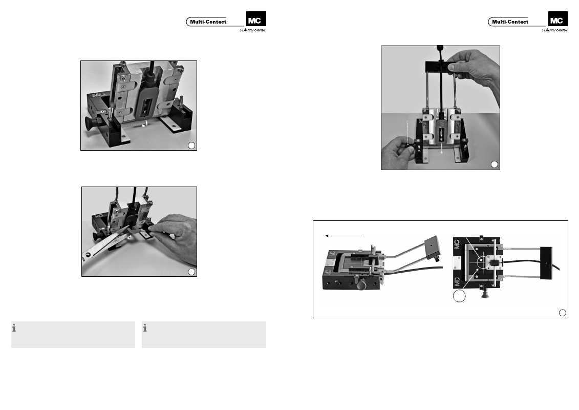
(ill. 17)
Nachdem die farbige Schutzfolie der Klebefolie abgezogen
ist, muss der Arretierbolzen “N” zurückgezogen werden� Zum
Zurückziehen des Arretierbolzens “N” wird dieser nach aussen
gezogen und gegen den Uhrzeigersinn bis zum Anschlag
gedreht�
Während des Zurückziehens des Arretierbolzens “N” sollte
die Paneldosenaufnahme festgehalten und in die waagrechte
Position geschwenkt werden�
(ill. 17)
After the coloured protective foil has been removed fron the
adhesive foil, the locking pin “N” must be withdraw� To with-
draw the locking pin “N”, this is pulled towards the outside
and turned antilockwise to the limit�
While pulling back the locking pin “N”, the junction box recep-
tacle should be held and pivoted into a horizontal position�
(ill. 18)
Jetzt wird die Paneldosenaufnahme bis zum Einrasten in
Pfeilrichtung geschoben. In dieser Position befindet sich die
Paneldose ca. 2 mm über der Oberfläche des PV-Moduls.
Zum Aufsetzen der Paneldose verwenden Sie einen z�B� zylin-
drischen Druckstempel� Positionieren Sie das Zentrum des
Druckstempels möglichst genau auf dem Schnittpunkt des
Positionierkreuzes� Drücken Sie mit dem Druckstempel das
Innenteil mindestens 5 Sekunden lang nach unten� Wenden
Sie dafür eine Anpresskraft von 700-800 N auf (Die Federkraft
des Innenteils beträgt 100 N).
(ill. 18)
The junction box receptacle is now pushed in the direction of
the arrow until it engages in place� In this position the junc-
tion box is approximately 2 mm above the surface of the PV
module� To apply the junction box, use, for example, a cylindri-
cal pressure pad� Position the center of the pressure pad as
accurately as possible on the section of the positioning cross�
Use the pressure pad to push the internal part down for at
least five seconds. Use a pressing-on force of 700-800 N (the
spring force of the internal part is 100 N).
Positionierkreuz für Druckstempel
Positioning cross for pressure pad
Druckstempel max� Ø 30mm bei einer Positioniergenauigkeit von ±1
Pressure pad max� Ø 30mm with a positioning accuracy of ±1
Verschieberichtung
Direction of movement