Ethernet / profinet interbus profibus – Multi-Contact MA213-04 Benutzerhandbuch
Seite 4
Advanced Contact Technology
4 / 8
www.multi-contact.com
B
S
Ethernet / Profinet
Interbus
Profibus
7
6
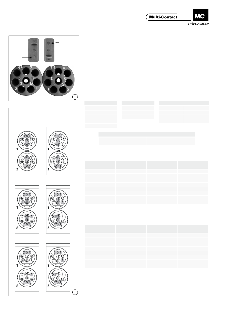
Kontakte in Einsatz montie-
ren
Contact assembly in inserts
(ill. 6)
Der Buchseneinsatz ist mit einem B,
der Steckereinsatz ist mit einem S
gekennzeichnet� Die Kontaktnummern
befinden sich auf der Rückseite der
Einsätze� Die Kontakte werden von der
Rückseite her eingeführt�
(ill. 6)
The female insert is marked with a B,
the pin insert is marked with an S� The
contact numbers are on the back side�
The contacts will be inserted from
back side�
Kontaktanordnung der Kon-
taktträger
Contact arrangement of the
contact carrier
(ill. 7)
(Von der Anschlussseite her gesehen)
(ill. 7)
(Seen from the termination side)
Konfiguration mit 4 Paaren T568A
Configuration with 4 pairs T568A
Konfiguration mit 4 Paaren T568B
Configuration with 4 pairs T568B
Steckerseite
Buchsenseite
Pin side
Socket side
Interbus
DO
1
/DO
2
DI
3
/DI
6
COM
4
Profibus
Line A
1
Line B
2
GND
4
Ethernet & Profinet
TX+
1
TX-
2
RX+
3
RX-
6
CANbus
Individuelle Konfiguration nach
Bus-Spezifikation
Individual configuration accor-
ding to BUS specifications
Kontakt No.
Contact No.
Paar No.
Pair No.
Farbe
Colour
1
1
weiss/grün
white/green
2
1
grün
green
3
2
weiss/orange
white/orange
4
3
blau
blue
5
3
weiss/blau
white/blue
6
2
orange
orange
7
4
weiss/braun
white/brown
8
4
braun
brown
Tab. 2
Tab. 3
Kontakt No.
Contact No.
Paar No.
Pair No.
Farbe
Colour
1
1
weiss/orange
white/orange
2
1
orange
orange
3
2
weiss/grün
white/green
4
3
blau
blue
5
3
weiss/blau
white/blue
6
2
grün
green
7
4
weiss/braun
white/brown
8
4
braun
brown