Multi-Contact MA210 Benutzerhandbuch
Seite 6
Advanced Contact Technology
6 / 8 www.multi-contact.com
16
17
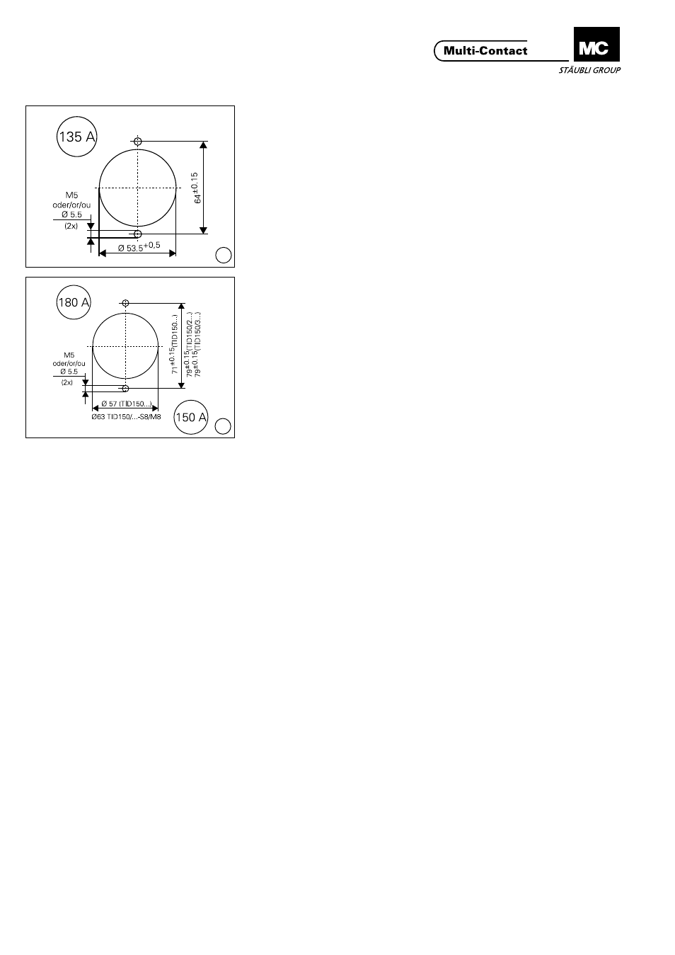
Steckverbinder-Montage
Assembly of plug connector
(ill. 16)
TID-S6/M5
Bohrungen gemäss Bohrplan anferti-
gen�
Einbaudose auf Vorderseite der Mon-
tagefläche aufschrauben.
(ill. 16)
TID-S6/M5
Drill holes according to drilling plan�
Screw receptacle on to front assembly
surface�
(ill. 17)
TID150-S8/M8, TID150/2-S8/M8,
TID150/3-S8/M8
Bohrungen gemäss Bohrplan anfer-
tigen� Einbaudose auf Vorderseite der
Montagefläche aufschrauben.
(ill. 17)
TID150-S8/M8, TID150/2-S8/M8,
TID150/3-S8/M8
Drill holes according to drilling plan�
Screw receptacle on to front assembly
surface�
Anschlussstecker-Montage
Assembly of plug connector
(ill 18)
Bohrpläne für den direkten Einbau
der Einzelstecker S6���/S8���/S12��� in
die Stromanschlüsse primärseitig am
Transformator und für die Fixierung
der Aufbaugehäuse TAG��� auf der
Transformatorenplatte� Diese dienen
der Kontaktierung der Flanschstecker
TSB���
Anzugsdrehmomente für Einzel-
stecker:
S6 = 2,5 ±0,5 Nm,
S8 = 4,5 ±0,5 Nm,
S12 = 8 ±0,5 Nm
(ill. 18)
Drilling plan for the direct installation
of the individual plug pins S6���/S8���
/S12��� to the primary terminal board
of the transformer and for the installa-
tion of the panel mounting housings
TAG��� onto the plate of transformer�
Matching parts are flanged female
plugs TSB���
Tightening torque for individual plug:
S6 = 2,5 ±0,5 Nm,
S8 = 4,5 ±0,5 Nm,
S12 = 8 ±0,5 Nm