Multi-Contact MA275 Benutzerhandbuch
Seite 6
Advanced Contact Technology
6 / 8
www.multi-contact.com
2 - 6
x
12,2
12,2
+0, 2
- 0,1
+0, 2
- 0,1
15
13
14
(ill. 13)
Führen Sie die Litze des abisolierten
Kabels ein, bis der Kabelmantel (Iso-
lation) am Crimp-Einsatz anschlägt.
Schliessen Sie die Crimpzange soweit
bis diese wieder geöffnet werden
kann. Öffnen Sie den Klemmbügel
und ziehen Sie das vercrimpte Kontak-
telement heraus.
(ill. 13)
Insert the stripped cable end until the
insulation comes up against the crimp
insert. Close the crimping pliers com-
pletely, until the ratchet mechanism
cycles completely and the handle
releases. Open the clamp and take out
the crimped contact element.
(ill. 14)
Kontrollieren Sie die Vercrimpung
visuell. Entspricht diese nicht Ihren
Prüfanforderungen, ist das Kontaktele-
ment zu entfernen und erneut bei
ill. 10 zu beginnen.
(ill. 14)
Visually check the crimp. Verify that
the crimp is fully closed, contains all
of the conductor strands, is sym-
metrical and is not poorly formed in
any way. If not, remove the crimp by
cutting it off and start over at ill. 10.
Hinweis:
Die Anweisung zur korrekten
Handhabung der Crimpzange
PV-CZM... entnehmen Sie bitte der
Bedienungsanleitung MA251 auf
www.multi-contact.com
Note:
For directions on the operation of
the crimping tool PV-CZM..., please
see operating instructions MA251 at
www.multi-contact.com
Spezielle Sicherheitshinweise
für das Crimpen
Special safety notes regard-
ing crimping
Gefahr:
Crimpen Sie keine Kabel, deren
Isolationen bereits beim Abisolie-
ren beschädigt wurden!
Falls die Kabelisolation an einer
Stelle beschädigt ist, muss der
betreffende Teil des Kabels abge-
schnitten werden und die Litze
nochmals auf das erforderliche
Mass abisoliert werden.
Danger:
Do not crimp cables with insula-
tions that were damaged while
stripping!
In case of damage at the cable
isolation the damaged cable
section has to be cut off and
removed. The cable has to be
stripped again.
Hinweis:
Bitte achten Sie auf eine Gehäuse-
wanddicke von minimal 2 mm und
maximal 6 mm. Bei einer Unterschrei-
tung der Gehäusewanddicke von
2 mm ist der Einsatz des Produktes
durch den Kunden abzuprüfen.
Note:
Please ensure a housing wall
thickness not less than 2 mm and a
maximum of 6 mm. In case of using
a wall thickness below 2 mm the
validation process has to be done by
the customer.
Montage der Kupplungen
Installation of receptacles
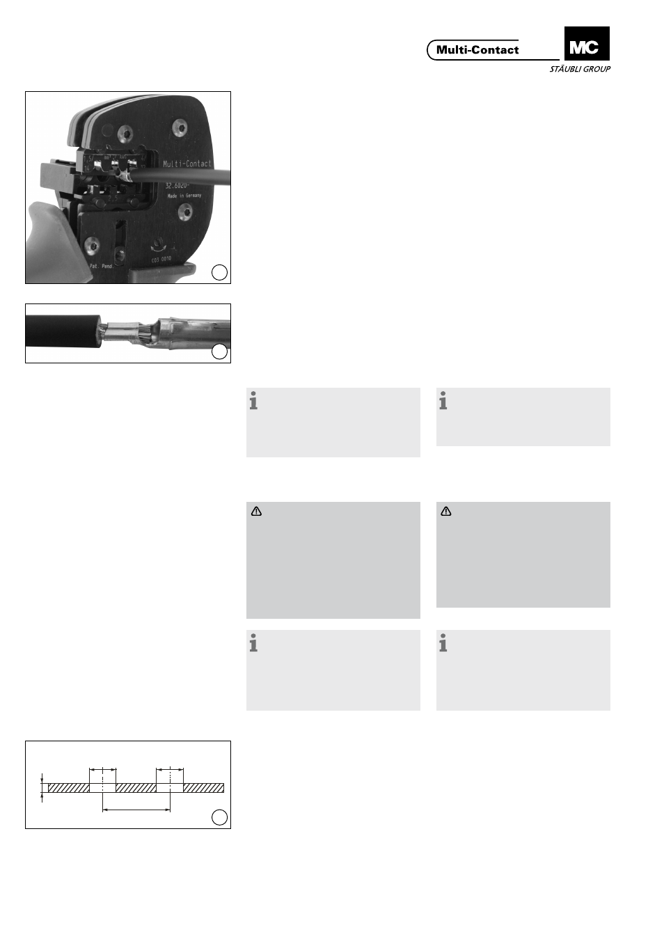
(ill. 15)
Bohren Sie die Gehäusewand.
Empfohlenes Bohrungsmaß siehe
Zeichnung. (das vormals angegebene
Maß 12,5
+0,2/-0,4
mm ist machbar, soll
jedoch in der Endanwendung verifi-
ziert werden). Alle Bohrungskanten
müssen anschliessend sauber entgra-
tet werden!
(ill. 15)
Drill the panel wall. Recommended
bore dimension see in the sketch. (the
formally indicated dimension
12,5
+0,2/-0,4
mm ist possible, but shall
be verified in the end use). Subse-
quently, burrs must be removed from
the edges of all bores!
Bei Horizontal- oder Vertikal-Einbau
wird ein Rasterabstand (X) von min-
destens 25 mm empfohlen.
For both horizontal and vertical
mounting a spacing (X) of at least
25 mm is recommended.