Standby led, Standby switch, Remote sensor – ROTEL RSP985 Benutzerhandbuch
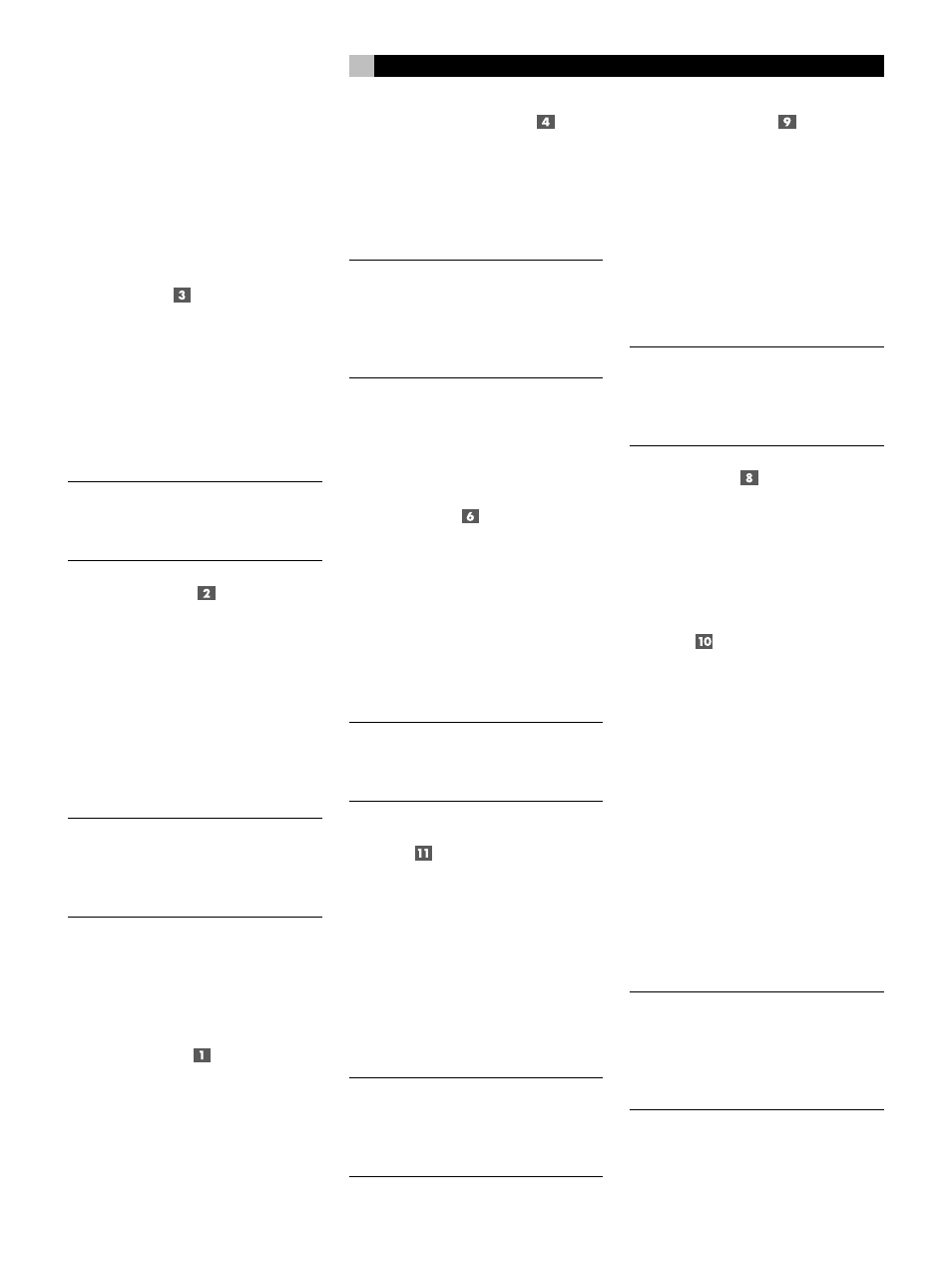
Seite 11: Master volume control, Tone controls, Listening input source buttons, 1 channel input, Tape monitor, Recording input source buttons
11
Most functions are duplicated on the front panel
and on the handheld remote control, a few
only on one or the other. These duplications
are noted below. In addition, when two ref-
erence numbers appear, one refers to the lo-
cation of the button on the front panel, the other
to the location of the button on the handheld
remote control.
Standby LED
Some of the RSP-985’s circuitry (microprocessor,
infrared sensor, etc.) remains powered at all
times, while the rest of the circuitry is turned
on or off by the user. The STANDBY LED lights
whenever the RSP-985 is plugged into a live
AC outlet but does not necessarily mean that
the RSP-985 is totally active. If other front panel
LEDs are lit, then the RSP-985 is fully functional.
NOTE
: During system setup, it is possible to
select an alternative FULLY-ON power-up
mode in which the unit is fully activated when-
ever it is connected to a live AC outlet.
Standby Switch
Similar to a power switch in function, this button
switches the RSP-985 from standby mode to
fully active mode. If only the STANDBY LED is
lit, push the front panel (or handheld remote
POWER button) to fully activate the RSP-985.
Other front panel LEDs light up and a welcome
screen will appear on your TV set. Push the
STANDBY switch again to deactivate the
RSP-985. You'll see that only the STANDBY LED
remains lit.
NOTE
: The STANDBY switch also controls the
rear panel AC power outlets. When the
RSP-985 is in STANDBY mode, the AC out-
lets are off. When the RSP-985 is functional,
the AC outlets are live.
The operation of the STANDBY switch is some-
what more elaborate when using the RSP-985’s
ZONE 2 capability. For a detailed explana-
tion, see the ZONE 2 Connections and Op-
erations section of this manual.
Remote Sensor
This sensor receives infrared signals from the
handheld remote control. Make sure you do
not accidentally block this sensor with cables
or accessories.
Master Volume Control
Turn this control clockwise to raise and coun-
terclockwise to lower the volume to all six main
output channels simultaneously.
MASTER VOLUME buttons are also available
on the RSP-985's handheld remote control.
NOTE
: The MASTER VOLUME control is me-
chanically connected to an internal servomo-
tor and responds to commands from the
handheld remote. It will rotate in the appro-
priate direction automatically when adjusting
the volume from the remote control.
Use the position of the LED indicator on the
knob’s outer edge to determine relative vol-
ume settings. When the volume control LED
blinks, you’ve engaged MUTE from the remote
controller.
Tone Controls
BASS and TREBLE controls increase and de-
crease the audio signal’s low and high fre-
quency content. Rotate each one clockwise
to increase output in the respective frequency
range and counterclockwise to reduce it. The
center detent removes each control from the
audio path for maximum signal integrity. The
ON-SCREEN DISPLAY will show tone control
settings as you adjust them.
NOTE
: The BASS and TREBLE controls are by-
passed in THX mode and will have no effect,
regardless of the setting indicated by the ON-
SCREEN DISPLAY.
Listening Input Source
Buttons
Six front panel pushbuttons select an audio/
video input source such as a CD player, VCR,
Laser Disc Player, etc. Push any of these but-
tons (or the duplicates on the handheld remote)
to select the desired source. You will hear this
source and, if you have selected a video source,
see its picture on your TV. An LED indicator
on each pushbutton lights to confirm your se-
lection. In addition, the ON-SCREEN DISPLAY
confirms your selection.
NOTE
: The source inputs can accommodate
either analog signals or digital signals. This
selection is made from the ON-SCREEN
MENU system during initial setup of the sys-
tem.
5.1 Channel Input
This button overrides all other audio inputs and
directly connects an external adaptor to the
RSP-985’s MASTER VOLUME control and audio
outputs. Press this button to listen to the audio
input from a 5.1 channel decoder. An LED
above the button will light to indicate your
selection. All of the RSP-985’s circuitry is by-
passed, except the MASTER VOLUME control.
The 5.1 CHANNEL button is duplicated on
the handheld remote control.
NOTE
: The 5.1 Channel Input is an audio-only
signal. The video signal from the selected
source remains active. The 5.1 Channel in-
put signal is not available for recording or
for Zone 2.
Tape Monitor
This switch overrides the normal Listening
Source Selectors to listen to whatever source
component is connected to the Tape Monitor
Input jacks. A confirming LED will light when-
ever the Tape Monitor switch is depressed.
Recording Input Source
Buttons
The RSP-985 allows you to listen to and/or
watch one source while simultaneously record-
ing from a second source. For example, you
could listen to a CD while recording from a
DVD player to a VCR. The row of RECORD-
ING front panel buttons allows you to select
the analog input from any source for record-
ing. Its signal is routed to the rear panel VIDEO
2, 3, and 4 outputs and has no effect on the
source selected for listening. LEDs immediately
above each pushbutton light to confirm your
selection.
The handheld remote does not have RECORD-
ING buttons. However, a recording selection
can be made from the remote using the ON-
SCREEN MENU system.
NOTE
: The RECORD inputs accept only ana-
log signals. Thus, if you are using a digital
connection from a CD player or DVD for lis-
tening, you should also connect an analog
signal for recording. See the section on Rear
Panel Input Connections.
English