Connecting edge finder output, and input signals, Ii - 1 installation, and electr ical connection – HEIDENHAIN ND 780 Benutzerhandbuch
Seite 210
86
II Technical Information
II - 1 Installation, and Electr
ical Connection
Connecting Edge Finder Output, and Input
Signals
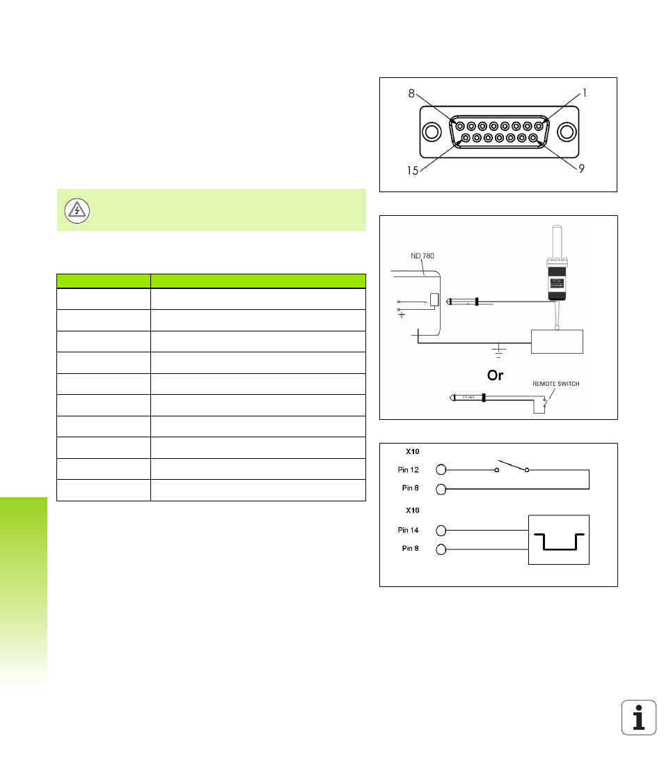
Connect the HEIDENHAIN Edge Finder to the D-sub input X10 on the
rear panel.
Adapt ND 780 for use with the Edge Finder through the following
operating parameters:
Stylus length
Stylus diameter
For description of operating parameters, .
Pin layout for Edge Finder, and Measured Value Output input (for
pinout)
Pins 12, and 14 are used in conjunction with the Measured Value
Output feature. When either of these contacts are shorted to Pin 8
(0V) the measured values as defined in Job Setup are output over the
TXD line of the RS-232 interface. A commercially available switch can
be used to provide the contact between pin 12, and 8. The pulse input
between pin 14, and pin 8 can be initiated with a TTL logic device (i.e.
SN74LSXX).
The operator must enter new edge finder settings.
Pin
Assignment
1
0 V (Inner shield)
2
KTS Ready
3
Signal for IOB
6
DC 5 V
7
0 V
8
0 V
9
Signal for IOB
12
Value Output Contact
13
KTS
14
Value Output Pulse