X1 x 2 x 3 – Multi-Contact MA213-01 Benutzerhandbuch
Seite 11
Advanced Contact Technology
www.multi-contact.com
11 / 12
Ø3.5
3.
3
5.
2
44
X
1
X
2
X
3
7.
9
7.
9
45
Blindstopfen
Blind plug
Beispiel / Example: MVS1
Montagerichtung
Mounting direction
(ill. 44)
Einbau der Blindstopfen
(ill. 44)
Assembly of blind plugs
Tab. 3
Tab. 3
Bl
indstopf
en
Bl
ind plugs
Ø
Einsetz-
/ Ausbau-
W
erkzeug
Insertion
/ Extraction
tool
Bestel
l-No.
Order No.
K
ontr
ol
l-Mass
Contr
ol d
imension
CT-BS1
1
MSA-WZ-1/1,2
18.3002
3,5 mm – 5,1 mm
MVS1
1,5
MSA-WZ-1,5
18.3005
3,3 mm – 5,2 mm
MVS3
3
MSA-WZ-3
18.3012
1 mm – 1,6 mm
MVS5
6
MSA-WZ-5
18.3015
7,5 mm – 8,7 mm
CT-BS8
8
MSA-WZ-8
18.3022
2 mm
Kontrolle der Kontakt-Montage
Checking the contact assembly
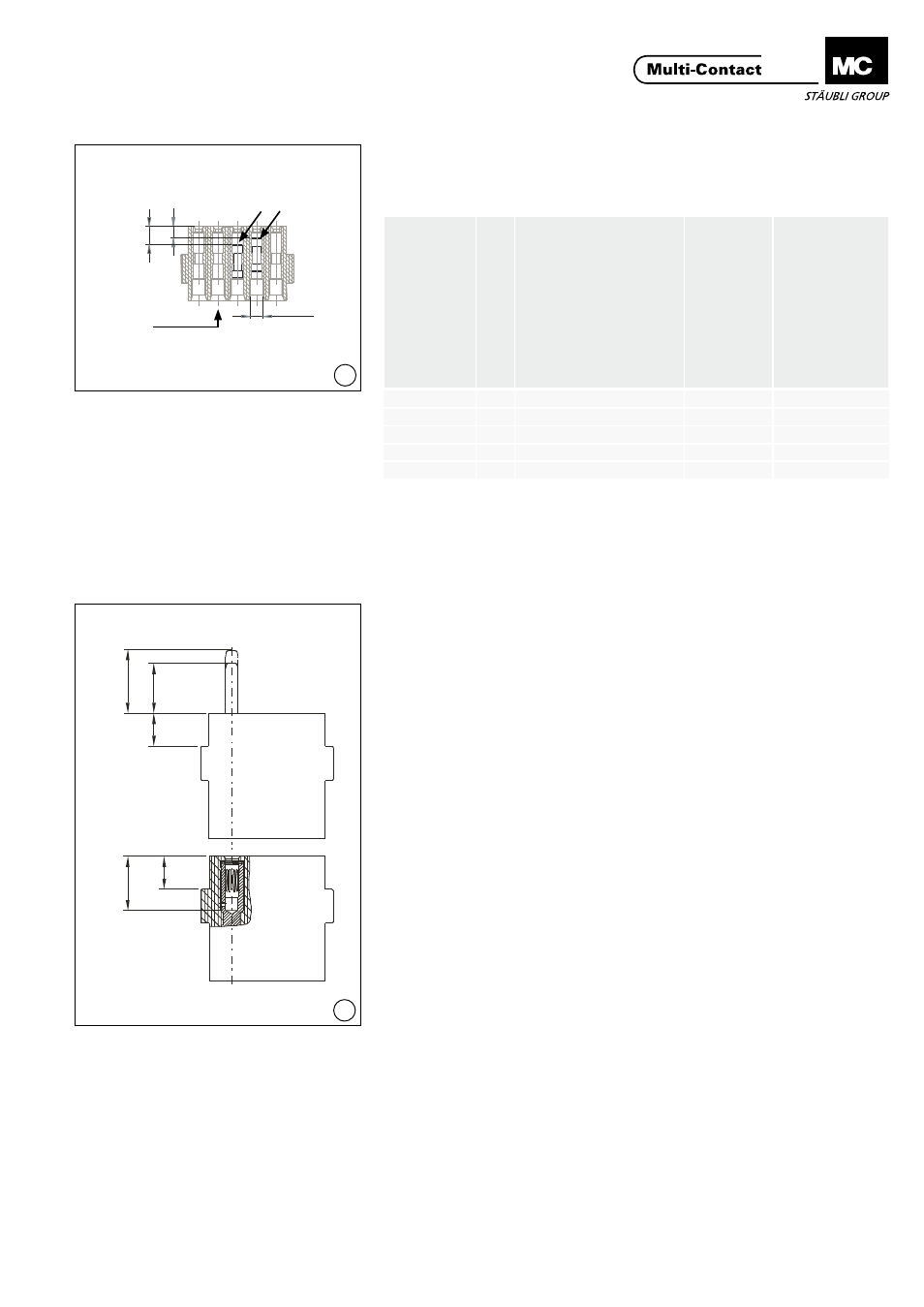
(ill. 45)
Das richtige Einrasten der Kontakte
muss mit den Massen X1 (Stift),
X2 (Stift, voreilend), und X3 (Buchsen)
kontrolliert werden�
(Siehe Tab� 4, Seite 12)�
(ill. 45)
The correct engagement of the
contacts must be checked with the
dimensions X1 (pin), X2 (pin, pre-
mating) and X3 (sockets)�
(See Tab� 4, page 12)�
Beim CT-0,6 wird das richtige Ein-
rasten der Kontakte in den Trägern
erreicht indem die Kontaktteile mit
dem entsprechendem Werkzeug bis
zum Anschlag eingepresst werden�
With the CT-0,6 the contacts are
correctly locked in the carriers by
pressing in the contact parts as far as
they will go with the appropriate tool�
Bei Belegungsfehlern oder Repara-
turen werden die Kontakte mit den
entsprechenden Ausbauwerkzeugen
aus den Kontaktträgern von der Steck-
seite her hinausgestossen und neu
eingesetzt (Ausbauwerkzeuge siehe
Seite 4)�
In the event of pin or socket assign-
ment errors or repairs the contacts
are pushed out of the contact carriers
from the plugging side using the ap-
propriate extraction tools and reinsert-
ed (extraction tools see page 4)�