Montage der leitungen cable assembly – Multi-Contact MA213-01 Benutzerhandbuch
Seite 6
Advanced Contact Technology
6 / 12
www.multi-contact.com
29
2)
30
31
max.21
2x
min.2
min.2
Nenn-Ø Stift / Buchse
Nominal Ø pin / socket
Leiterquerschnitt
Conductor cross section
Crimpzange / Crimping pliers
L1
CT-M-CZ
M-PZ-13
M-PZ-T2600
mm
mm
2
AWG
Selector
AWG-N°
Selector
SEL-N°
Locator
Einsatz / Insert
Einsatz / Insert
mm
Thermoelement-Kon-
takte
Thermocouple contacts
(DBP2-/DSP2/CT-BP1/CT-SP1)
0,14
26
26
1
MES-CZ
1)
-
-
4,5
0,2
24
24
2
MES-CZ
1)
-
-
4,5
0,34
22
22
3
MES-CZ
1)
-
-
4,5
0,5
20
20
4
MES-CZ
1)
-
-
4,5
0,6
0,14
26
26
1
MES-CZ-CT0,6
-
-
5
0,6
0,25
24
24
2
MES-CZ-CT0,6
-
-
5
1
0,25
24
24
2
MES-CZ-CT1
-
-
4,5
1
0,5
20
20
4
MES-CZ-CT1
-
-
4,5
1
0,75
18
18
5
MES-CZ-CT1
-
-
4,5
1,5
0,5
20
20
4
MES-CZ-CT1,5
-
-
4,5
1,5
1
18
18
5
MES-CZ-CT1,5
-
-
4,5
1,5
1,5
16
16
6
MES-CZ-CT1,5
-
-
4,5
3
2,5
14
14
7
MES-CZ-CT3
-
-
8
3
4
12
12
8
MES-CZ-CT3
-
-
8
6
6
10
-
-
-
MES-PZ-TB-5/6
-
10
6
10
8
-
-
-
MES-PZ-TB-8/10
TB8-17
10
6
16
6
-
-
-
MES-PZ-TB-9/16
TB9-13
10
8
10
8
-
-
-
MES-PZ-TB-8/10
TB8-17
10
8
16
6
-
-
-
MES-PZ-TB-9/16
TB9-13
10
8
25
4
-
-
-
MES-PZ-TB-11/25
TB11-14,5
10
8
35
2
-
-
-
-
TB9-13
12
8
50
1/0
-
-
-
-
TB11-14,5
23
12
50
1/0
-
-
-
-
TB11-14,5
23
12
70
2)
2/0
-
-
-
-
TB8-17
26
12
95
2)
3/0
-
-
-
-
TB20
28
Tab. 1
1)
Der Locator MES-CZ kann auch für Nenn-Ø
Stift/Buchse von 1 mm – 3 mm verwendet
werden�
1)
The locator MES-CZ can also be used for nomi-
nal Ø pin/socket from 1 mm up to 3 mm.
(ill. 29)
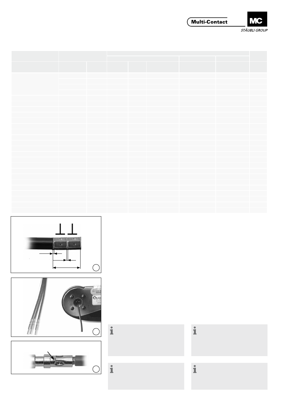
2)
Bei Crimpungen mit Leiterquerschnitt von
70 mm² oder 95 mm²
müssen zwei Quetschun-
gen nebeneinander durchgeführt werden�
(ill. 29)
2)
In crimp terminations with a conductor
crosssection of 70 mm² or 95 mm², two
pinches must be performed side by side�
Montage der Leitungen
Cable assembly
Crimpanschluss
Crimp connection
Crimpzange und Einsatz gemäss
Tab� 1�
Crimping pliers and insert according
to Tab� 1�
(ill. 30)
Einzelleiter in axialer Richtung in die
Crimphülse des Kontaktes bis zum
Anschlag einführen�
(ill. 30)
Insert wire into the contact crimping
sleeve as far as it will go�
Hinweis:
Für Kontakte mit Nenn-Ø 0,6 mm,
1 mm, 1,5 mm und 3 mm: Ange-
schlossene Leiter müssen vor und
nach dem Crimpen im Sichtloch der
Crimphülse sichtbar sein (ill. 31).
Note:
For contacts with nominal
Ø 0,6 mm, 1 mm, 1,5 mm and
3 mm: Wires must be visible in the
sight hole before and after crimping
(ill. 31).
Hinweis:
Der Crimpbereich muss nach
dem Leitungsanschluss mit dem
Schrumpfschlauch Bestell-Nr.
33.5666 isoliert werden.
Note:
After connecting the cable, the
crimp area must be insulated with
the shrink-on sleeve, order No.
33.5666.
Sichtloch
Sight hole