Installation, Overview of the interfaces, Setting up the device – Guntermann & Drunck DL-MUX4 Benutzerhandbuch
Seite 47: Overview of the interfaces setting up the device, English, Front panel of the kvm switch, Back panel of the kvm switch
Installation
G&D DL-MUX4 · 3
English
Installation
Connect the cables preferably block by block and from the bottom up. By doing so,
you will avoid already connected cables blocking your view of the interfaces.
Overview of the interfaces
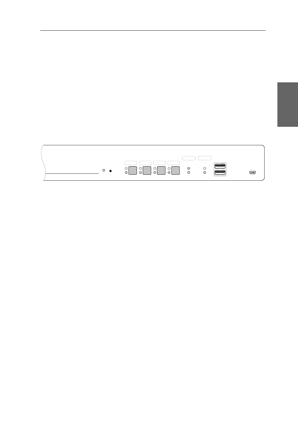
Front panel of the KVM switch
The front panel of the KVM switch provides two USB 2.0 interfaces to connect any
USB devices. USB devices such as a printer or a mass storage device connected to
the interfaces are available to the active computer.
The front panel also provides a Service socket. This interface is not relevant for oper-
ating the device.
Next to the interfaces, four buttons enable you to select the active channel. The front
panel also provides several LEDs (see Status displays on page 7) .
Back panel of the KVM switch
The back panel of the KVM switch provides interfaces to connect the console devices
and the computers. The following page contains a detailed description of these inter-
faces.
Setting up the device
1. Ensure that the computers, which are to be connected to the KVM switch, are
turned off. If the computers are provided with both keyboards and mouses,
unplug the cables of the input devices from the PS/2 or USB interfaces.
2. Place the KVM switch between the computers and the console. Please mind the
maximum cable length of five metres between the KVM switch and the computers
which are to be connected.
3. Before installing the KVM switch, decide which button on the front panel of the
device should be assigned to which computer.
Figure 1: Detailed front view of the KVM switch
Active
Status
Service
USB 2.0
Main
Power
Red.
Status
Switch
Ready
Ident.
CPU 1
CPU 2
CPU 3
CPU 4