Varyscan – JB-Lighting Varyscan 4 1200 HMI Benutzerhandbuch
Seite 35
35
Varyscan
®
4 1200 HMI
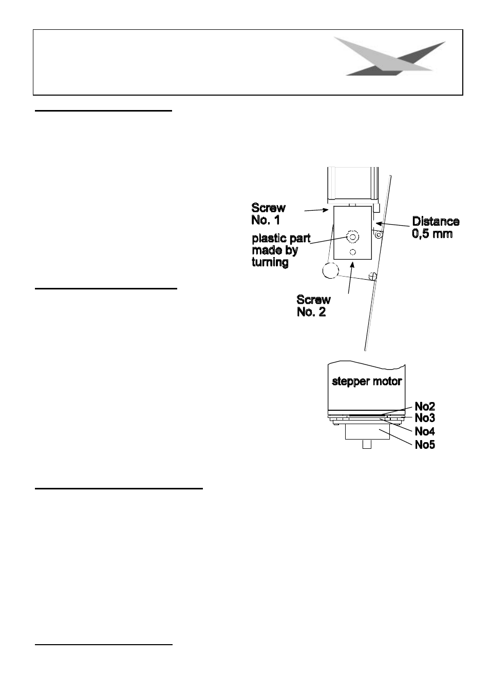
Adjustment of the mirror stop
To adjust the mirror of your Varyscan
®
1200 HMI, proceed as follows:
Adjust the initialisation mode at DIP - switch No.1 (DIP -switch position see page 7) and start your
Varyscan
®
. Now wait until the initialisation of the scan is ran through and all motors stopped. Then
loosen screw No.1 Now turn the holder for the y-
motor towards the stop up to a distance of 0,5
mm. Tighten screw No.1 now. During tightening
the screw pay attention to the correct adjustment
of the motor brake (see sketch below). Loosen
screw No.2 and turn the y-motor towards the
holder for the y-motor and adjust hereby a
distance of 0,5 mm between the stop and the
holder for the y-motor.
Adjustment of the motor brake
The motor brake is similar at each of the stepper
motors of the scan. There are three special parts
(part no. 2,3 and 4) which must be installed in the
following succession:
Part no. 1.
motor
Part no. 2.
Tellerfedern
Part no. 3.
Stahllaserteil
Part no. 4.
Kunststoffscheibe
Part no. 5.
zu montierendes Teil
Part no. 5 has to be pushed on the axis of the stepper motor until
the parts no. 2 can not be compressed anymore. After remove the
part no. 5 about 0,5 mm and turn the fastening screws. The "motor-
brake" is now optimum adjusted .
Regular Maintenance Performances
Warning: Before open the appliance pull out mains plug!
Open the casing by turning out the screws at the top of the Varyscan
®
.
To be able to take out the slide-in modules of your Varyscan
®
, you have to screw off two screws of
silver at the side-piece, up to the mark of the slide-in modules. Now you are able to take out the slide-
in modules (sketch page 4).
Attention:
Do not forget to lock in the slide-in modules after having completed
your maintenance performances, by screwing in the screws of silver
carefully!
1. Cleaning of all optical parts