Connecting the power supply – Guntermann & Drunck FIBREVision-USB 2.0 Benutzerhandbuch
Seite 40
Installation
11 · G&D FIBREVision-USB 2.0
USB 2.0 Trans. – Tx:
Insert the LC plug of a fibre optic cable.
Connect the other end of the cable to the USB 2.0 Trans. – Rx interface of the computer
module.
USB 2.0 Trans. – Rx:
Insert the LC plug of a fibre optic cable.
Connect the other end of the cable to the USB 2.0 Trans. – Tx interface of the computer
module.
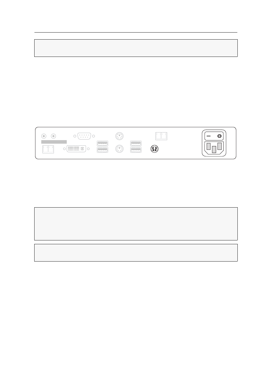
Connecting the power supply
Main Power:
Connect the supplied power cable to this interface.
Red. Power:
Use this socket to connect an optional power pack, which enables a sec-
ond, redundant power supply.
Additional interfaces of the multi-channel variants
Transmission
x
– Tx:
Insert the LC plug of a fibre optic cable.
Connect the other end of the cable to the Transmission
x
– Rx interface of the compu-
ter module.
Transmission
x
– Rx:
Insert the LC plug of a fibre optic cable.
Connect the other end of the cable to the Transmission
x
– Tx interface of the compu-
ter module.
DVI/VGA Out
x
:
Connect the local console monitor to this interface.
If the monitor provides an analog VGA input, connect an optional adapter to this
interface. Afterwards, connect the monitor’s VGA cable to the adapter.
NOTE:
Remove the protection caps from the Transmission interface and the cable
plugs.
NOTE:
For each additional video channel, the multi-channel variants of the user
module are additionally provided with the interfaces listed below.
The interfaces of each channel are located next to each other. The interfaces are
provided with the numbers of the channels.
NOTE:
Remove the protection caps from the Transmission interface and the cable
plugs.
Main
Power
Red. Power
Rx
USB 2.0 Trans.
Tx
Class 1 Laser Product
Rx
Transmission
Tx
DVI/VGA Out
Keyb.
Mouse
RS232
Speaker Micro In
USB 2.0 Devices
USB Keyb./Mouse