Multi-Contact MA095 Benutzerhandbuch
Seite 6
Advanced Contact Technology
6 / 20
www.multi-contact.com
14
15
Tab. 3
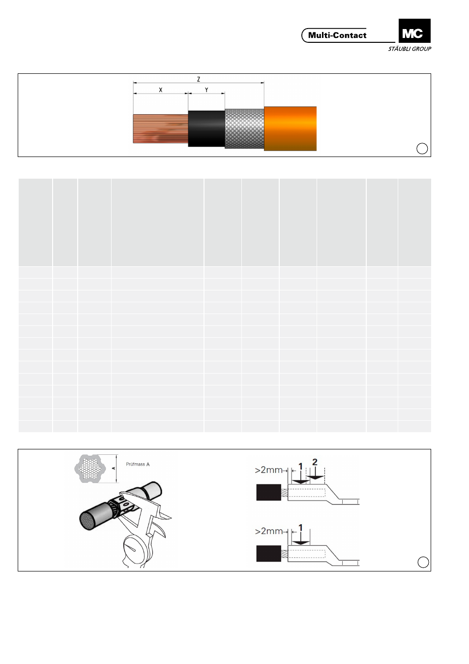
(ill. 14)
Leitung abisolieren�
(ill. 14)
Strip cable insulation�
Elpress-Einsatz
Elpress insert
Für Leitungstyp, Klasse
1)
For cable type, class
Leiter
quer
schnitt
Conductor cr
oss section
(mm
2
)
Crimphülse
Crimp slee
ve
Mass X
2)
Dimension
2)
(mm)
Mass Y
2)
Dimension
2)
(mm
Mass Z
2)
Dimension
2)
(mm
Back
enhal
ter
Ja
w clamp
Anzahl Crimpstel
len
3)
Number of crimping points
3)
Prüfmass A
3)
Contr
ol d
imnension A
3)
(mm)
B14
5
50
H50-H07RN-F/16BV-NS
27
50
100
V1330
1
11�6
B16
5
70
H70-H07RN-F/16BV-NS
27
50
96
V1330
1
13�2
B18
5
95
H95-H07RN-F/16BV-NS
29
50
100
V1330
1
14
B19
5
120
H120-H07RN-F/16BV-NS
30
38
98
V1330
1
15�4
B22
5
150
H150-H07RN-F/16BV-NS
33
36
98
V1330
1
16�3
13CB24
5
185
H185-H07RN-F/16BV-NS
38
33
98
ohne/without
2
17�7
13CB26
5
240
H240-H07RN-F/16BV-NS
42
28
96
ohne/without
2
19�5
B14,5
6
50
H50/16BV-NS
27
50
100
V1330
1
11�4
B17
6
70
H70/16BV-NS
27
50
100
V1330
1
13�4
B20
6
95
H95/16BV-NS
30
50
100
V1330
1
16�4
B22
6
120
H120/16BV-NS
30
38
96
V1330
1
16�3
B25
6
150
H150/16BV-NS
33
36
98
V1330
1
20�3
13CB27
6
185
H185/16BV-NS
38
33
98
ohne/without
2
20�5
13CB30
6
240
H240/16BV-NS
42
28
98
ohne/without
2
23�3
1)
gemäss VDE 0295 / According to VDE 0295
2)
siehe ill� 14 / see ill� 14
3)
siehe ill� 15 / see ill� 15
(ill. 15)
Leitung mit allen Einzeldrähten in die Crimphülse einführen�
Die Leitung muss im Sichtloch (Querbohrung in der Crim-
phülse) sichtbar sein� Crimphülse vercrimpen mit Crimpzange
Elpress V1311C und dem richtigen Einsatz (siehe Tab� 3)�
Crimpzone beachten!
(ill. 15)
Insert lead into the crimping sleeve with all strands� The wire
must be visible in the sight hole (crosswise hole in the crimping
sleeve)� Crimp crimping sleeve with Elpress V1311C tool and
the appropriate insert (see Tab� 3)�
Observe crimping zone!