3 devices in the technirouter family – TechniSat TechniRouter 9/2x4 G Benutzerhandbuch
Seite 29
29
EN
3 Devices in the TechniRouter Family
3.1 TechniRouter 9/1x8 G (Art. No. 0000/3294) and 9/2x4G (Art. No. 0000/3296)
These multiswitches are used as base
units for distribution. They switch the
signals from two satellite positions (8
satellites IF banks) to up to 8 subscribers.
They make either 8 or 4 output channels
(per cable) in the IF frequency band
950…2150 MHz available. The individual
subscribers gain unrestricted access to
all digital programs.
In the satellite field, the subscriber lines have a strong and slope-equalized amplification.
The terrestrial and the return path are passive and flat over the frequency.
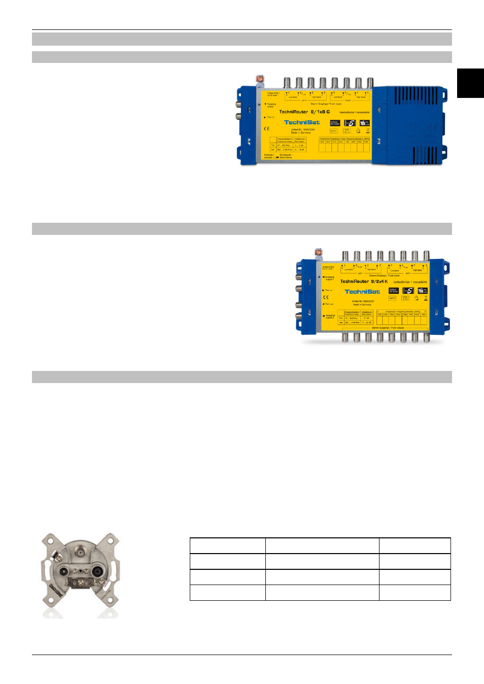
3.2 TechniRouter 9/1x8 K (Art. No. 0000/3295) and 9/2x4 K (Art. No. 0000/3297)
This cascading matrix for 8 subscribers is installed
together with a base unit (TechniRouter 9/1x8 G or
9/2x4 G) and when used with an intermediate
amplifier, up to four additional units can be cascaded
in series.
The current supply is provided from the base unit onto
all trunk cables in the cascade, in doing so its slide
switch must be in position "cascade". The current
supply is passed without internal cross-linking.
3.3 Accessories
All sockets, distributors and amplifiers must be compatible for the Sat IF domain and
include a DC bypass. For wall sockets, a
DC-bypass in the trunk-line and a diode-decoupled DC-bypass in the tap must be
present.
The terminal socket, likewise, must have a diode-decoupled DC-bypass too.
The DC outlet is required for the power supply for the TechniRouter and to transmit the
control signals. The diode decouples the power supplies of the receivers.
It is recommended to possibly use only one diode in the line between receiver and
TechniRouter.
Single cable wall socket with DC-Thru, decoupled with diode
TechniPro
Tap loss
Art. No.
600-10
10 dB
0000/3180
600-13
13 dB
0000/3181
600-20
20 dB
0000/3184