BECKHOFF BK5100 Benutzerhandbuch
Seite 36
Anhang
36
BK5100
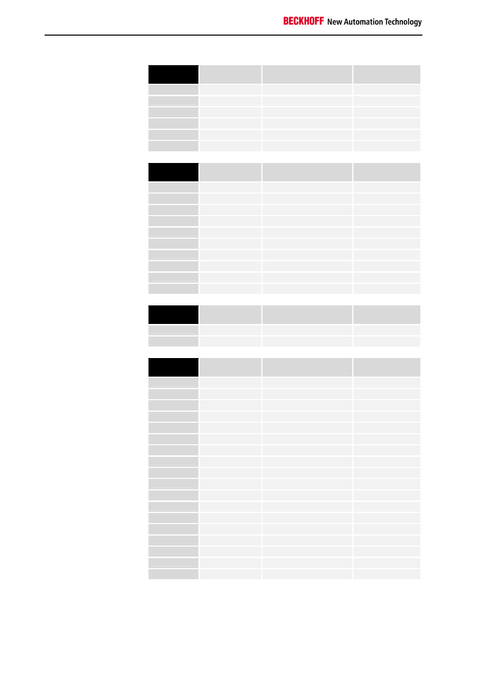
Teil für byteorientierte
Daten, Analoge Ausgänge
relative
Byteadresse
Bitposition
Prozeßabbild in der
Steuerung
Position im Block
0, 1
keine
A0, A1
POS11
2, 3
keine
A2, A3
POS11
4, 5
keine
A4, A5
POS12
6, 7,
keine
A6, A7
POS12
8, 9
keine
A8, A9
POS20
10, 11
keine
A10, A11
POS20
Teil für bitorientierte Daten,
Digitale Ausgänge
relative
Byteadresse
Bitposition
Prozeßabbild in der
Steuerung
Position im Block
12
0
A12
POS07
12
1
A12
POS07
12
2
A12
POS08
12
3
A12
POS08
12
4
A12
POS09
12
5
A12
POS09
12
6
A12
POS18
12
7
A12
POS18
13
0
A13
POS19
13
1
A13
POS19
Teil für byteorientierte
Daten, Analoge Eingänge
relative
Byteadresse
Bitposition
Prozeßabbild in der
Steuerung
Position im Block
0, 1
keine
E0, E1
POS10
2, 3
keine
E2, E3
POS13
Teil für bitorientierte Daten,
Digitale Eingänge
relative
Byteadresse
Bitposition
Prozeßabbild in der
Steuerung
Position im Block
4
0
E4
POS01
4
1
E4
POS01
4
2
E4
POS02
4
3
E4
POS02
4
4
E4
POS03
4
5
E4
POS03
4
6
E4
POS04
4
7
E4
POS04
5
0
E5
POS05
5
1
E5
POS05
5
2
E5
POS06
5
3
E5
POS06
5
4
E5
POS15
5
5
E5
POS15
5
6
E5
POS16
5
7
E5
POS16
6
0
E6
POS17
6
1
E6
POS17
Die Positionen POS14 und POS21 sind in bezug auf den Datenaustausch
nicht relevant. Sie erscheinen nicht in der Liste. Wird ein Byte nicht voll-
ständig genutzt, z.B.: E8, füllt er Buskoppler die restlichen Bits des Bytes
mit Nullen auf.