Installation, Overview of the interfaces, Mounting the device – Guntermann & Drunck DVIMUX8-OSD-USB Benutzerhandbuch
Seite 72: Overview of the interfaces mounting the device, Front panel of the kvm switch, Back panel of the kvm switch
Installation
3 · G&D DVIMUX8-OSD-USB
Installation
Overview of the interfaces
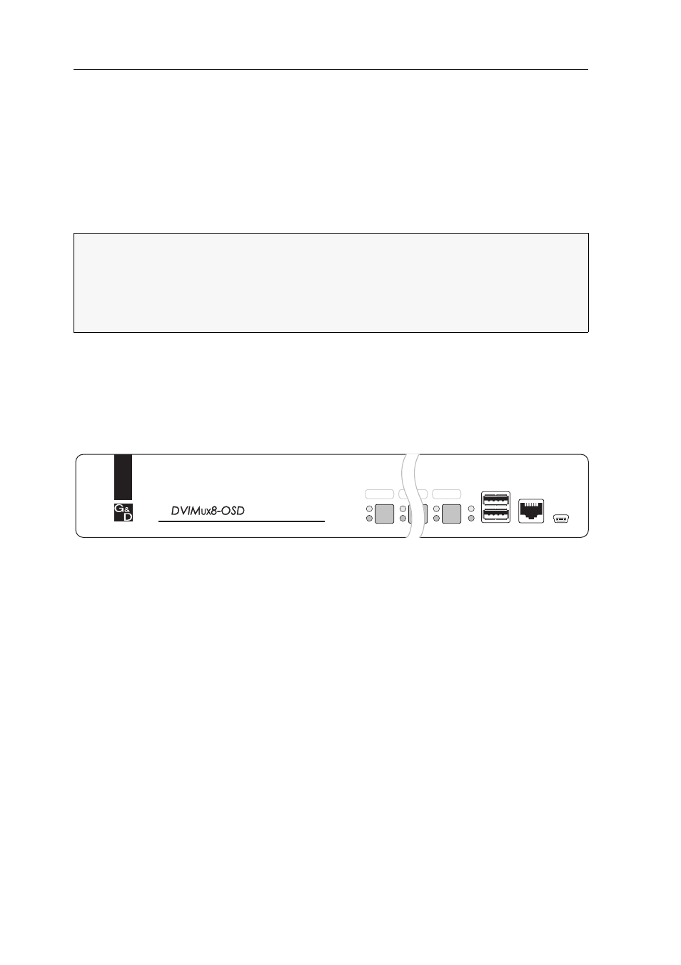
Front panel of the KVM switch
The front panel of the KVM switch provides two USB 2.0 ports to connect any
USB 2.0 devices.
The front panel also provides an RS232 and Service socket.
You can use the RS232 port to connect a serial device (for example a special keypad)
to switch the active channel. Detailed information on this topic is given on page 20.
The Service socket helps you update the firmware and is used by the support team to
query different device parametres.
The front panel also provides multiple LEDs (see Status displays on page 7) and eight
buttons to select the active channel.
Back panel of the KVM switch
The back panel of the KVM switch provides ports to connect the console devices
and the computers. On the following pages, the ports are described in detail.
Mounting the device
1. Turn off the computers you want to connect to the KVM switch. Now, unplug
any keyboard and mouse cables from the USB interfaces.
2. Place the KVM switch between the computers and the console. Mind the maxi-
mum cable length of five metres between the KVM switch and the computers
you want to connect.
3. Before installing the KVM switch, decide which button on the front panel of the
device you want to assign to which computer.
NOTE:
USB devices such as a printer or a mass storage device connected to one of
these interfaces are available to the computer of the active channel.
After enabling the USB hold function (see page 47) the USB devices can be perma-
nently switched to,a defined computer (see page 13). The switching of the USB
devices maintains the same when switching the KVM channel.
Figure 1: Front view of the KVM switch
Active
Status
CPU 1
USB 2.0
Devices
User
CPU 8
CPU 7
RS232
Service