5 pin-belegung – HEIDENHAIN MSE 1000 Benutzerhandbuch
Seite 169
Advertising
Technische Spezifikationen
Pin-Belegung
Betriebsanleitung
169
14.5
Pin-Belegung
14
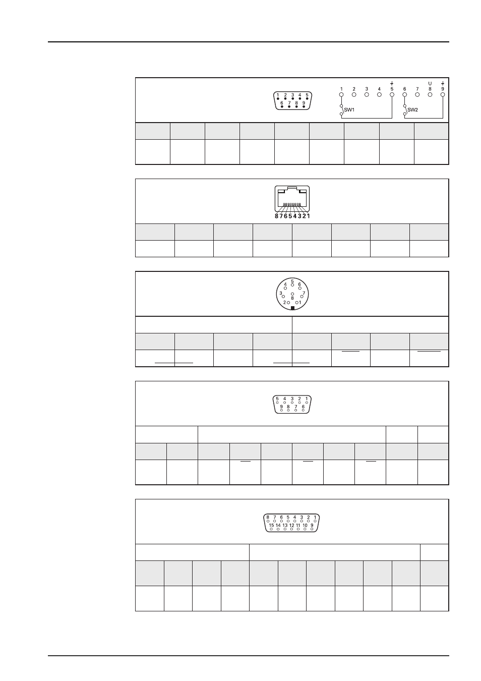
X103
Foot switch
MSE 1114, MSE 1124, MSE 1184
1
2
3
4
5
6
7
8
9
Switch 1
NO
/
/
/
GND
Switch 2
NO
/
DC 3.3 V
GND
15
X116
RJ-45
MSE 1114, MSE 1124, MSE 1184
1
2
3
4
5
6
7
8
E0 Tx +
E0 Tx –
E0 Rx +
/
/
E0 Rx –
/
/
16
X11 ... X14
EnDat
8-pin coupling, M12
MSE 1114, MSE 1314, MSE 1318
Power supply
Absolute position values
8
2
5
1
3
4
7
6
U
P
Sensor
U
P
0 V
Sensor
0 V
DATA
DATA
CLOCK
CLOCK
17
TTL
MSE 1124, MSE 1324, MSE 1328
Power supply
Incremental signals
Others
Shield
7
6
2
3
4
5
9
8
1
Housing
U
P
0 V
U
a1
U
a1
U
a2
U
a2
U
a0
U
a0
/
Case
GND
18
1 V
PP
MSE 1184, MSE 1384, MSE 1388
Power supply
Incremental signals
Others
4
12
2
10
1
9
3
11
14
7
5/6/8/
13/15
U
P
Sensor
U
P
0 V
Sensor
0 V
A+
A-
B+
B-
R+
R-
/
Advertising