Optional: connecting the local console, Connections for data transmission and power supply – Guntermann & Drunck FIBREVision Benutzerhandbuch
Seite 81
Installation
8 · G&D FIBREVision
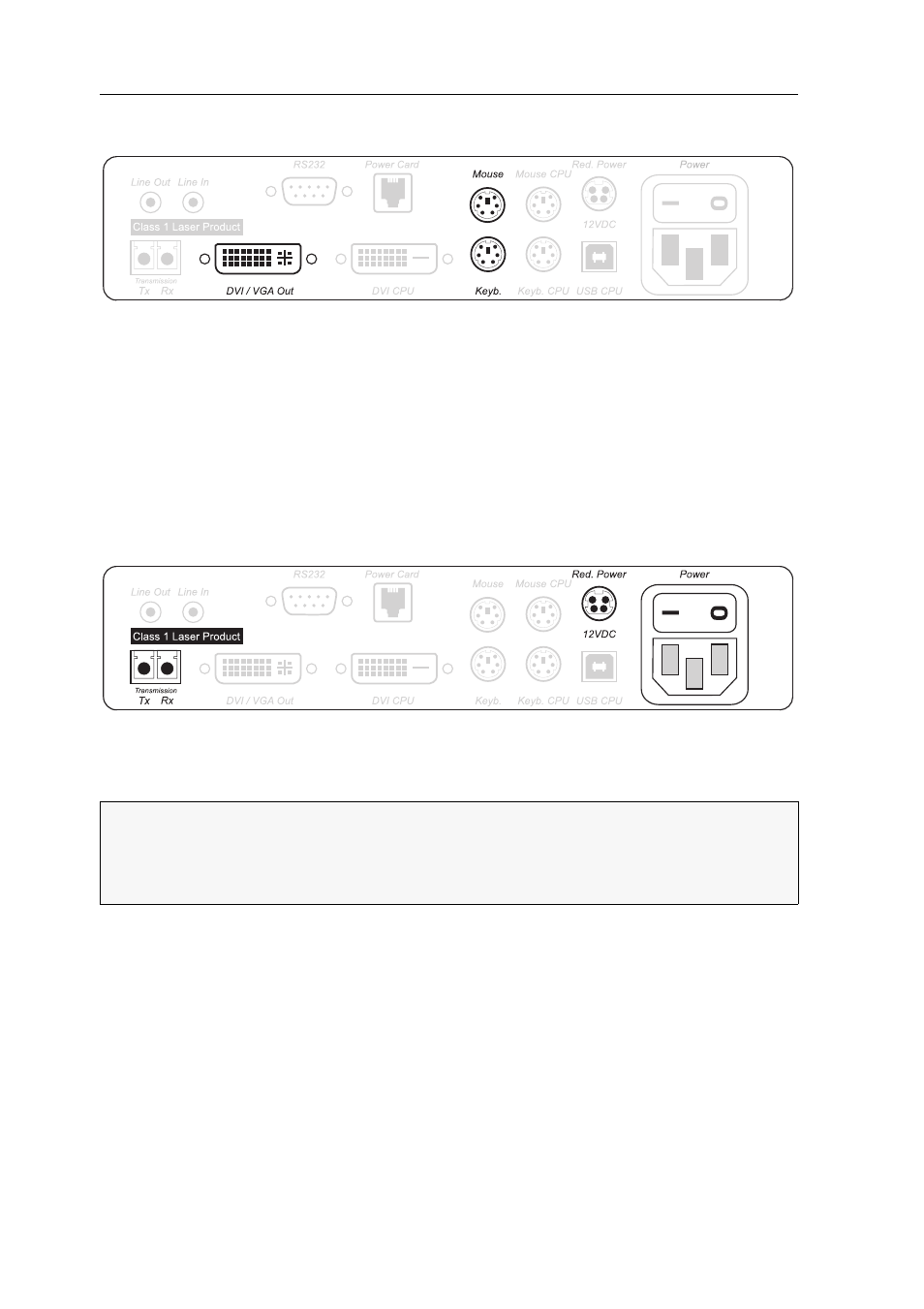
Optional: Connecting the local console
DVI/VGA Out: Connect the monitor of the local console to this interface.
If the monitor only provides an analog VGA input, connect an optional adapter to this
interface. Afterwards, connect the monitor’s VGA cable to the adapter.
Keyb.: Connect the keyboard of the local console to this interface.
Mouse: Connect the mouse of the local console to this interface.
Connections for data transmission and power supply
Remove the protection cap from both the Transmission interface and the cable plugs.
Transmission – Tx: Insert the LC plug of the fibre optic cable (available as accessories)
into this interface. Connect the other end of the cable to the Transmission – Rx inter-
face of the user module.
Transmission – Rx: Insert the LC plug of the fibre optic cable (available as accessories)
into this interface. Connect the other end of the cable to the Transmission – Tx inter-
face of the user module.
Power: Insert the supplied PowerCable-2 Standard IEC cable.
Red. Power: Connect the Power-Set 12/Type 2 power pack to establish a second, redun-
dant power supply for the computer module.
Figure 2: Interfaces to connect the local console to the computer module
Figure 3: Interfaces
for data transmission and power supply
IMPORTANT:
The device uses components with laser technology which comply
with laser class 1. Although class 1 laser are considered as being nonhazardous,
direct eye contact is to be avoided. Do not stare into the beam or view directly
with optical instruments.