Ivoclar Vivadent IPS e.max CAD Chairside v.1 Benutzerhandbuch
Seite 62
10
1.5
1.0
1.5
1.5
1.5
1.5
1.5
1.0
1.0
1.5
1.5
1.5
6°
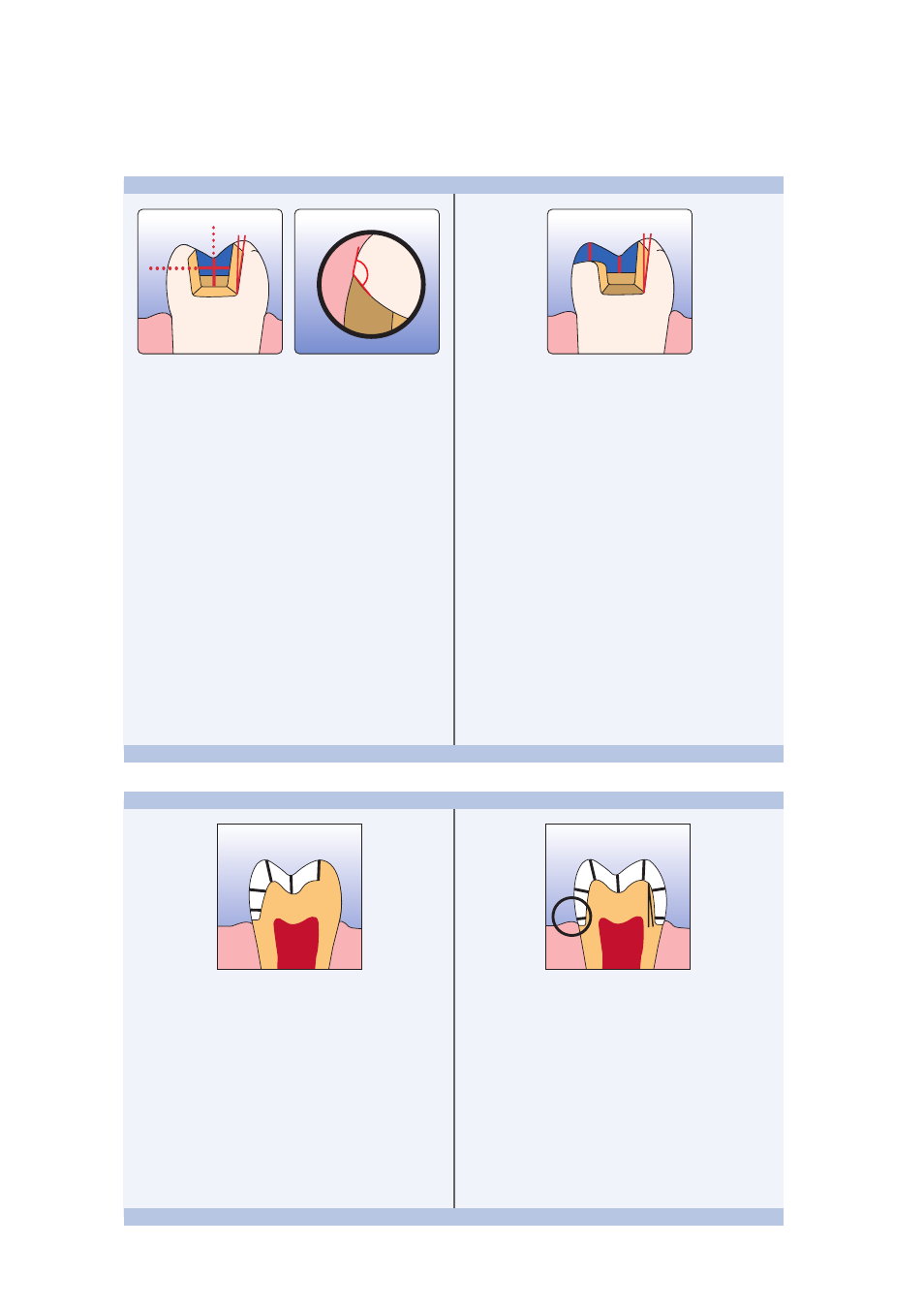
– Static and dynamic antagonist contacts must be taken
into consideration.
– The preparation margins must not be located on
centric antagonist contacts.
– Provide at least 1.5 mm of reduction in the cusp
areas.
– Prepare a circular shoulder with rounded inner edges
or a deep chamfer. Width of the shoulder/chamfer
should be at least 1.0 mm.
– Reduce the anatomical shape and observe the
stipulated minimum thickness. Prepare a circular
shoulder with rounded inner edges or a deep chamfer.
Width of the shoulder/chamfer at least 1.0 mm.
– Reduce the incisal crown third by approx. 1.5 mm.
– Reduce the buccal or lingual area by approx. 1.5 mm.
– For conventional and/or self-adhesive cementation, the
preparation must demonstrate retentive surfaces.
Partial crown
Posterior crown
1.0
1.0
6°
100-120°
6°
1.0
1.0
– Static and dynamic antagonist contacts must be taken
into consideration.
– The preparation margins must not be located on
centric antagonist contacts.
– A preparation depth of at least 1.0 mm and an
isthmus width of at least 1.0 mm must be observed in
the fissure area.
– Prepare the proximal box with slightly diverging walls
and observe an angle of 100°-120° between the
proximal cavity walls and the prospective proximal
inlay surfaces.
For inlays with pronounced convex cavity walls with-
out adequate support by the proximal shoulder,
marginal ridge contacts should be avoided.
– Round out internal edges in order to prevent stress
concentration within the ceramic material.
– Do not prepare slice-cuts/bevels or feather edges.
– Static and dynamic antagonist contacts must be taken
into consideration.
– The preparation margins must not be located on
centric antagonist contacts.
– A preparation depth of at least 1.0 mm and an isthmus
width of at least 1.0 mm must be observed in the
fissure area.
– Prepare the proximal box with slightly diverging walls
and observe an angle of 100°-120° between the
proximal cavity walls and the prospective proximal
onlay surfaces.
For onlays with pronounced convex cavity walls with-
out adequate support by the proximal shoulder,
marginal ridge contacts should be avoided.
– Round out internal edges in order to prevent stress
concentration within the ceramic material.
– Do not prepare slice-cuts/bevels or feather edges.
– Provide at least 1.0 mm of reduction in the cusp areas.
Inlay
Onlay