Pin assignment of the rs232 socket/interface – Guntermann & Drunck DL-Vision(M/S) Benutzerhandbuch
Seite 110
Advertising
Background information
44 · G&D DL-Vision(M/S)
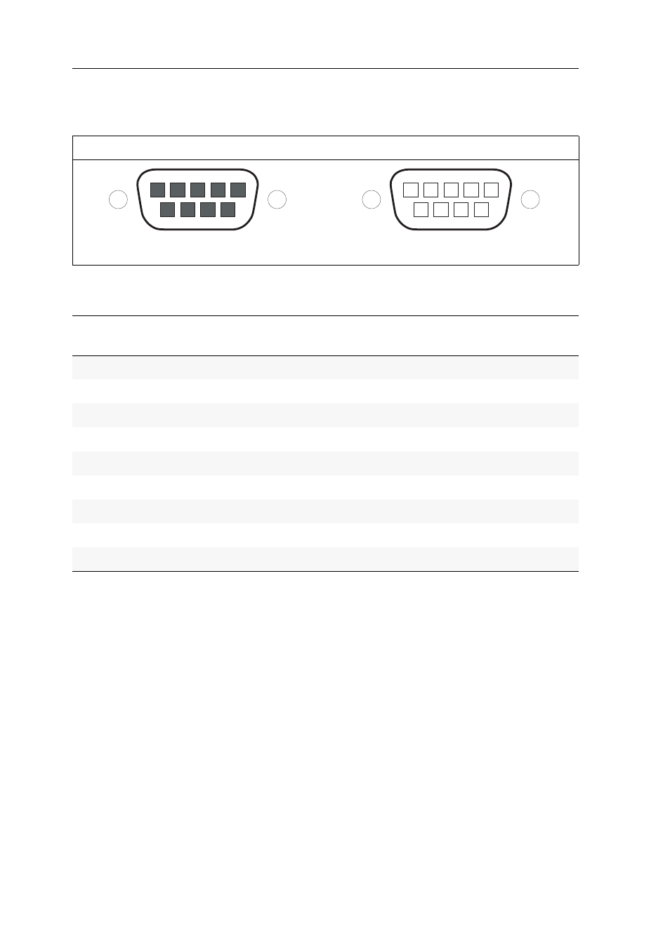
Pin assignment of the RS232 socket/interface
The following figures show the pin assignments of RS232 plug and RS 232 socket:
The table shows how the different conduits of the data connection are assigned to
the according pins:
User module
Computer module
RS232 plug
RS232 plug
Pin no.
Conduit
user module
computer
module
1
DCD (Data Carrier Detect)
Input
Output
2
RxD (Receive Data)
Input
Output
3
TxD (Transmit Data)
Output
Input
4
DTR (Data Terminal Ready)
Output
Input
5
GND (Ground)
Ground
Ground
6
DSR (Dataset Ready)
Input
Output
7
RTS (Request to Send)
Output
Input
8
CTS (Clear to Send)
Input
Output
9
not occupied
n/c
n/c
4 5
8
6
9
1 2 3
7
1
2
4
5
8
6
7
9
3
Advertising
Dieses Handbuch ist für die folgenden Produkte bezogen werden: