Installing the user module, Establishing the power supply, The remote console is connected to the – Guntermann & Drunck DL-Vision(M/S) Benutzerhandbuch
Seite 76: Dl-vision-con, Config panel
Installation
10 · G&D DL-Vision(M/S)
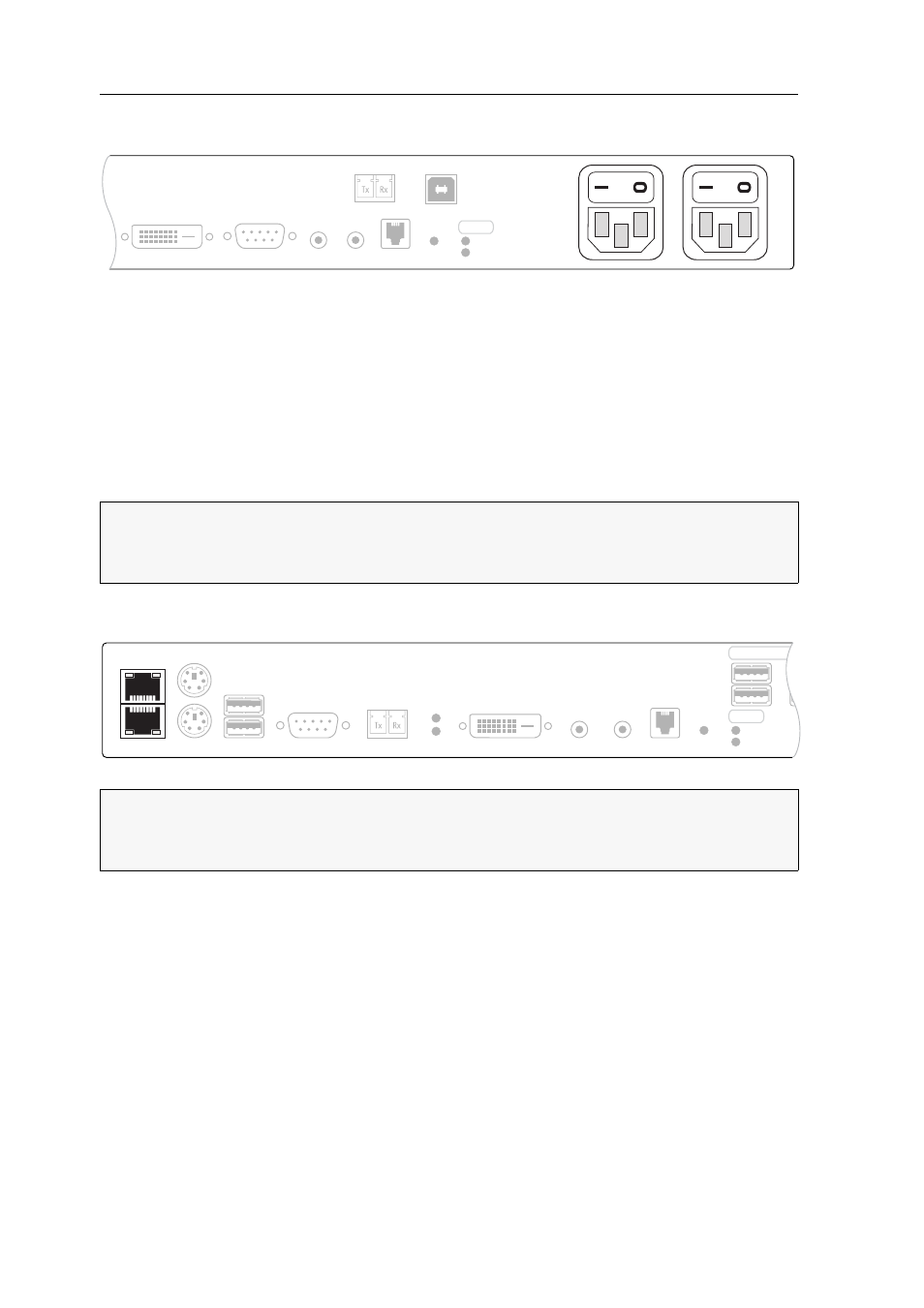
Establishing the power supply
Main Power: Insert one of the supplied PowerCable-2 Standard IEC cables here.
Red. Power: Insert one of the supplied PowerCable-2 Standard IEC cables here. This
establishes a second, redundant power supply for the user module.
Installing the user module
The remote console is connected to the
DL-Vision-CON
user module. The computer
connected to the computer module can be operated over this console.
Establishing a connection to up to two local networks
Network A: Insert a category 5 twisted pair cable (or better), which is available as acces-
sory. Connect the other end of the cable to the local network.
Network B: Insert a category 5 twisted pair cable (or better), which is available as acces-
sory. Connect the other end of the cable to the local network.
ADVICE:
Connect the cables to the computer module preferably from left to right.
By doing so, you will avoid already connected cables blocking your view of the
interfaces.
NOTE:
If desired, connect the network interface to up to two local networks. Now
you can not only access the
Config Panel
web application from those networks but
also send syslog messages to those networks.
Red. Power
Main Power
USB 2.0 CPU
RS232
DVI-D DL CPU
Line In Line Out Power Card
Power
Red.
Main
USB 2.0 Trans.
Ident.
Network B
Network A
RS232
DVI-D DL Out
Micro In
Speaker
Control Panel
Video
Link
USB K/M
Transmission
Keyb.
Mouse
USB 2.0 D
Power
Red.
Main
Ident.