Allocating the connection cable for the panel – Guntermann & Drunck DL-Vision(M/S) Benutzerhandbuch
Seite 114
Advertising
The DLV-Power expansion
48 · G&D DL-Vision(M/S)
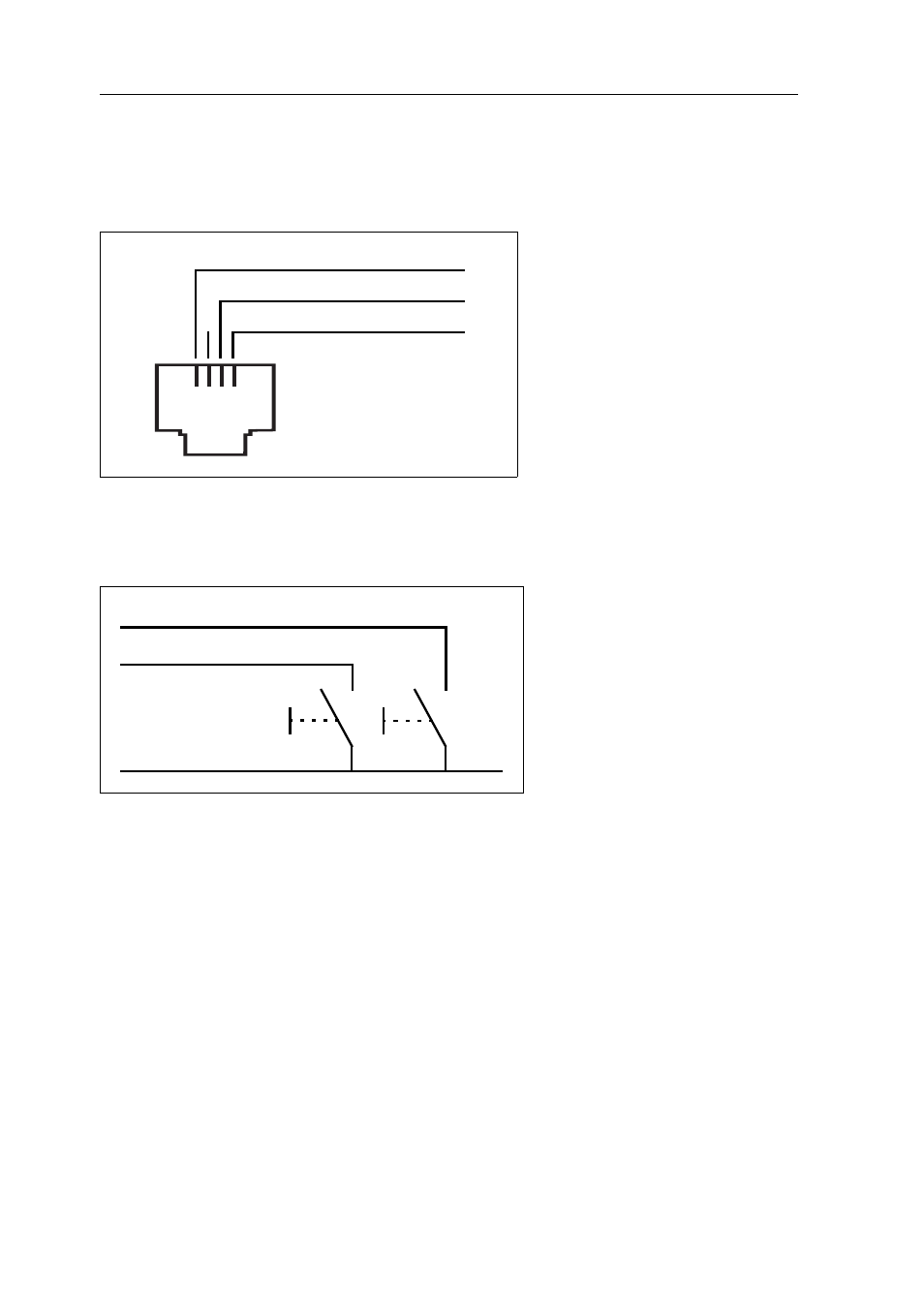
Allocating the connection cable for the panel
The connection cable, which is provided in the scope of delivery has to be fixed to
the panel. The following figure illustrates how the pins are assigned to the panel’s
functions:
To switch one of the ATX-Power or Reset signals, the signal has to be conductively
connected to the shared minus contact (pin 4):
Figure 1: Pin assignment to the functions of the panel
Figure 2: Basic circuit with buttons for ATX-Power and Reset
1 2 3 4
I1 SW1_ATXPWR# (Pin 1)
I2 SW2_RESET# (Pin 3)
- 0V (Pin 4)
I1 SW1_ATXPWR# (Pin 1)
I2 SW2_RESET# (Pin 3)
- 0V (Pin 4)
Advertising
Dieses Handbuch ist für die folgenden Produkte bezogen werden: