Bedienung, Gasflußdiagramm, Gaskonsole – Hypertherm HT4400 Benutzerhandbuch
Seite 56
Advertising
BEDIENUNG
2
HT4400
Betriebsanleitung
4-7
SVC
SV-13
FL3
PRESSURE FEEDBACK
PRESSURE FEEDBACK
Rotary Selector Switch #1
Rotary Selector Switch #2
SV-10
SV-11
SV-9
SV-8
PG-2
SV-12
Valve Cluster
PG-1
MV-1
SV-2
MV-2
MV-3
SV-4
MV-4
SV-3
SV-1
FL2
SV-6
MV-6
SV-7
MV-7
FL4
MV-5
SV-5
Air
Plug
Plug
Shield Cutflow
Plasma Cutflow
Plasma Preflow
Shield Preflow
Gas Console
O2
Plug
N2
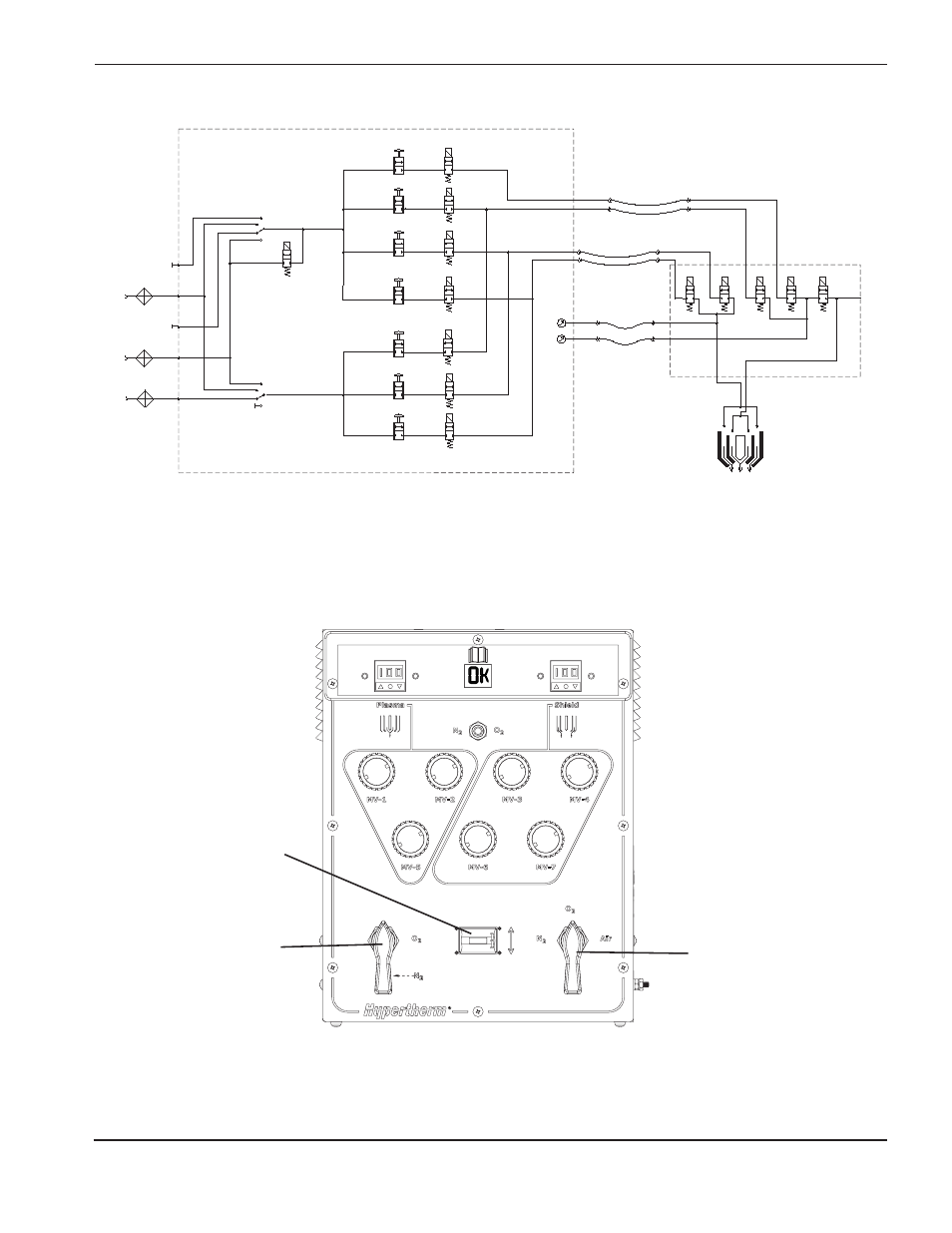
Gasflußdiagramm
(under lever)
Gaskonsole
Anmerkung:
Bei Leckprüfung 1 sind Ventile 1-7 eingeschaltet (geöffnet) und Ventile 8-12 ausgeschaltet (geschlossen).
Bei Leckprüfung 2 sind Ventile 8-12 eingeschaltet (geöffnet) und Ventile 1-7 ausgeschaltet (geschlossen).
Gasauswahl 1
Ventilauswahl
Gasauswahl 2
Advertising
Zie ook andere documenten in de categorie Hypertherm Ausstattung:
- THC ArcGlide (Seiten: 200)
- Plasma Arc Marking System (Seiten: 91)
- MAXPRO200 Rev.1 (Seiten: 271)
- MAXPRO200 Rev.1 (Seiten: 220)
- HPR800XD Auto Gas (Seiten: 350)
- THC X-Y Table Torch Height Control (Seiten: 152)
- THC Robotic System (Seiten: 92)
- HRT (Seiten: 64)
- HyIntensity Fiber Laser Rev.2 (Seiten: 200)
- HD3070 Plasma Arc Cutting System w/ Automatic Gas Console (Seiten: 258)
- HD3070 Plasma Arc Cutting System w/ Manual Gas Console (Seiten: 202)
- HD4070 Rev.1 (Seiten: 275)
- HPR130 Auto Gas Preventive Maintenance Program (Seiten: 229)
- HPR130 Manual Gas Preventive Maintenance Program (Seiten: 186)
- HPRXD Short Torch with Integrated Lead Rev.1 (Seiten: 30)
- HPR260 Auto Gas (Seiten: 298)
- HPR260 Manual Gas (Seiten: 243)
- DuraChill 5 HP (Seiten: 30)
- HT4001 (Seiten: 243)
- HySpeed HT2000 Plasma Arc Cutting System Rev.24 (Seiten: 249)
- HT2000LHF (Seiten: 168)
- MAX200 Machine Torch Plasma Arc Cutting System (Seiten: 160)
- MAX200 Hand Torch Plasma Arc Cutting System (Seiten: 167)
- HSD130 Remote High Frequency Console (Seiten: 195)
- Powermax1250 Rev.1 (Seiten: 72)
- Powermax30 Rev.1 (Seiten: 68)
- Powermax105 Rev.0 (Seiten: 343)
- Powermax1650 Rev.1 (Seiten: 69)
- Powermax1650 Troubleshooting Guide (Seiten: 66)
- Powermax600 Rev.2 (Seiten: 59)
- Powermax1100 Rev.1 (Seiten: 42)
- Powermax30 Rev.2 (Seiten: 67)
- Powermax1250 Rev.4 (Seiten: 84)
- Powermax1000 Rev.1 (Seiten: 78)
- Powermax1000 Rev.1 (Seiten: 68)
- Powermax85 Rev.2 (Seiten: 162)
- Powermax45 Rev.1 (Seiten: 102)
- Powermax45 Rev.1 (Seiten: 136)
- Powermax85 Rev.1 (Seiten: 248)
- Powermax30 AIR Rev.1 (Seiten: 68)
- Powermax125 Rev.1 Service manual (Seiten: 327)
- Powermax30 XP Rev.1 Service manual (Seiten: 211)
- ProNest (Seiten: 26)
- PHC (Seiten: 54)