Error compensation, Linear error compensation, Ii - 2 installation set up – HEIDENHAIN ND 780 Benutzerhandbuch
Seite 215
ND 780
91
II - 2 Installation Set
up
Error Compensation
The distance a cutting tool travels, measured by an encoder, can in
certain cases, differ from the actual tool travel. This error can occur
due to ball screw pitch error, or deflection, and tilting of axes. This
error can either be linear, or non-linear. These errors can be
determined with a reference measurement system, e.g. the VM 101
from HEIDENHAIN, or with gauge blocks. From an analysis of the
error it can be determined which form of compensation is required,
linear, or non-linear error.
The ND 780 provides the opportunity to compensate for these errors,
and each axis can be programmed separately with the appropriate
compensation.
Linear Error Compensation
Linear error compensation can be applied, if the results of the
comparison with a reference standard show a linear deviation over the
whole measuring length. In this case the error can be compensated by
the calculation of a single correction factor.
To calculate the linear error compensation use this formula:
Correction factor LEC = ((S – M) / M) x 10
6
ppm
with:
Example:
If the length of the standard used is 500 mm, and the measured
length along the X-axis is 499.95, then the LEC for the X-axis is
100 parts per million (ppm).
LEC = ((500 – 499.95) / 499.95) x 10
6
ppm = 100 ppm
(rounded to
the nearest whole number).
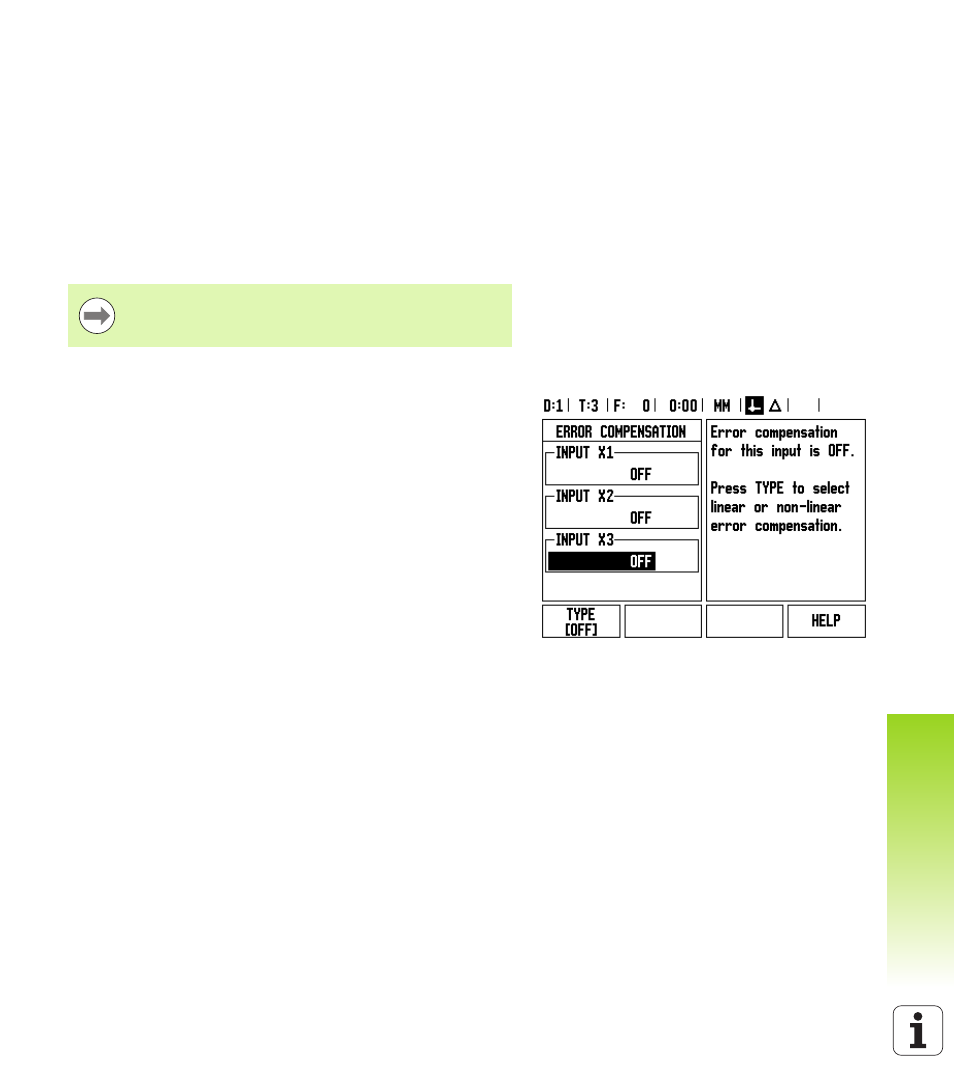
Once determined, the encoder’s error information is entered
directly. Press the TYPE soft key to select LINEAR compensation.
Enter the compensation factor in parts per million (ppm), and press
the ENTER key.
Error compensation is only available when using linear
encoders.
S
measured length with reference standard
M
measured length with device at axis