Non-linear error compensation, Setup procedure for non-linear error, Ii - 2 installation set u p – HEIDENHAIN ND 780 Benutzerhandbuch
Seite 216
92
II Technical Information
II - 2 Installation Set
u
p
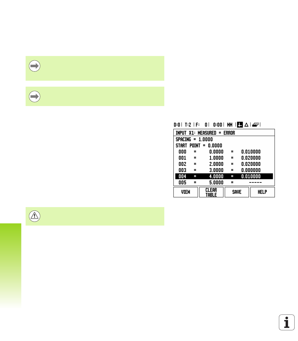
Non-Linear Error Compensation
Non-linear error compensation should be applied, if the results of the
comparison with a reference standard show an alternating, or
oscillating deviation. The required correction values are calculated, and
entered in a table. ND 780 supports up to 200 points per axis. The error
value between two entered adjacent correction points is calculated
with linear interpolation.
Setup procedure for Non-linear Error
The encoder has an inherent count direction. This may not reflect
the user defined count direction, and is only required for
determining the non-linear error compensation.
To establish the inherent count direction for any installed encoder on
a given axis, complete the following:
Open the Encoder Setup form, and select the encoder on the axis
that is to be addressed.
Arrow down to high light the count direction.
Use the POSITIVE/NEGATIVE soft key and select Positive. Press
enter.
Using the C key, return to the main display
Move the axis that the encoder is mounted on, and note the
direction of movement required for the positive direction.
The encoder’s inherent count direction is now established.
Non-linear error compensation is only available on scales
with reference marks. If non-linear error compensation has
been defined, no error compensation will be applied until
the reference marks have been crossed.
Non-linear error compensation must have values added
using the encoders inherent positive direction as of
software version 1.1.3.
Single reference mark encoders must cross the same
reference mark each time the DRO is powered on.